Most waterfront property owners operate under a dangerous assumption: that submersible dock lighting is simply standard household wiring placed underwater. It isn’t. This misconception leads directly to tripping GFCIs, corrosion, and worse — the electrical hazards that kill swimmers every year along the Gulf Coast and beyond.
The environment beneath a dock demands electrical practices that diverge sharply from what you’d do inside your home. You’re establishing a connection between 110-volt AC power and a permanently saturated space where saltwater or brackish conditions create exceptional electrical conductivity. The ABYC — American Boat and Yacht Council — developed the E-11 standard specifically because improper underwater wiring creates genuine risk of electrocution. Over two decades of building and repairing marine structures along the Gulf, I’ve observed what happens when corners get cut on this work. This guide covers every phase of installation correctly.
Why Dock Electrical Code Is Different From Household Wiring
The trap most DIYers fall into is treating dock circuits exactly as they would a porch or shed outlet. Residential wiring operates under the NEC — National Electrical Code. Dock installations must satisfy both the NEC and ABYC E-11 standards, with local municipalities often imposing additional restrictions on top of both. Throughout Florida, any new electrical installation on a dock requires permitting. If your structure sits above navigable waters, the Army Corps of Engineers may demand compliance documentation as well.
The separation between household circuits and marine circuits hinges on grounding and ground fault detection. Both ABYC E-11 and NEC Article 553 obligate GFCI safeguards for all 15- and 20-amp circuits and receptacles around dock areas. The logic behind this requirement extends beyond mere code fulfillment. Electric Shock Drowning — abbreviated ESD — develops when stray alternating current seeps into the surrounding water, establishing zones of electrical potential. Swimmers caught within these zones experience sudden paralysis of voluntary muscles, leading to submersion. Cases have occurred throughout our nation’s marinas, including documented fatalities right here on the Gulf.
The reassuring reality is that meticulous work renders this threat entirely avoidable. The fundamental principle guiding every choice below remains identical: construct a system permitting no detectable current escape into the water column. Each decision serves this protection.
Materials and Tools You Need Before You Start
Assemble everything required before making your first connection. Departing mid-installation to acquire forgotten items invites the exact conditions under which people establish provisional fixes they subsequently neglect to finalize. The following represents my standard inventory for equipping a typical residential pier with a submersible light assembly.
- 20-amp GFCI breaker or 20-amp GFCI outlet designated for wet conditions (typically $18–$35 retail depending on manufacturer)
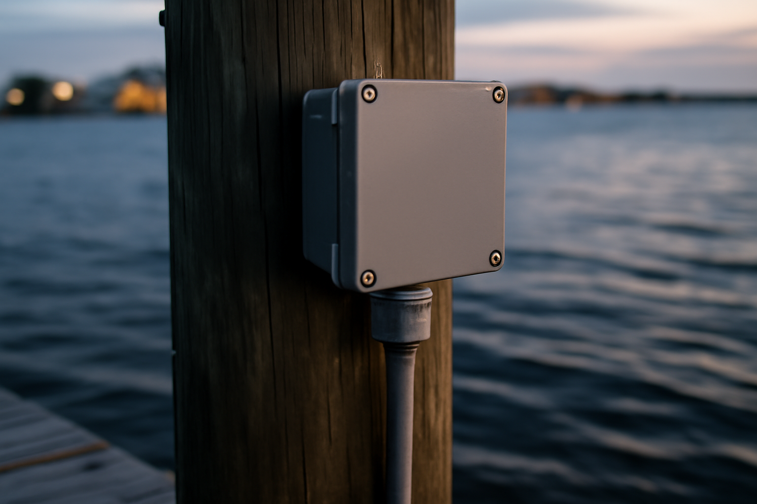
- Waterproof junction box carrying UL certification for wet or submerged environments — I favor stainless construction or UV-hardened polycarbonate options
- 12/2 or 12/3 UF-B (Underground Feeder) cable approved for direct burial in moist soil and permanent water exposure — budget $0.60–$0.90 for each foot
- Liquid-tight protective conduit and corresponding attachment hardware for sections above the waterline
- Commercial-duty heat-shrink butt connectors designed for saltwater environments — ordinary crimp connectors will not suffice
- Silicone self-fusing wrap and commercial electrical adhesive tape rated for marine exposure
- Wire stripping instruments, crimper apparatus, continuity meter, and touchless potential detector
- Stainless fastening clamps or UV-resistant restraint ties designed for securing cable runs to dock structural members
Never incorporate standard interior NM-B (Romex) cable into any section of this assembly. I’ve replaced submersible lighting on approximately a dozen installations where Romex was incorrectly selected. The outer sheath fails under combined UV and moisture stress in roughly two years’ time, exposing interior conductors to the surrounding damp. Invest supplementary funds in UF-B cable — it’s engineered specifically for these conditions.
How to Wire an Underwater Dock Light Safely — Step by Step
I’ll guide you through this process with appropriate deliberation. Skipping or hurrying any single component results in either recurring GFCI failures or systems posing genuine electrical danger. Dedicate a complete day if this represents your first time performing this work. Those with prior experience typically complete the installation in 180 to 240 minutes, though velocity offers no benefit in this context.
Step 1: Kill the Power and Verify It’s Off
Deactivate the breaker supplying current to your dock within the home’s main electrical box. Subsequently employ a non-contact voltage detector at either the dock’s electrical enclosure or disconnection switch to establish that no current flows through the circuit. I perform this confirmation in duplicate — immediately following the breaker shutdown, then again at the instant before commencing work. The procedure occupies minimal time. Neglecting this step carries unjustifiable danger.
Step 2: Install Your GFCI Protection at the Source
Should your dock installation lack GFCI safeguarding on the energized circuit, incorporate a GFCI device immediately. Installing a 20-amp GFCI breaker within the main service panel represents the optimal approach since it blankets the entire cable run in protection. Alternatively, position a certified GFCI outlet rated for outdoor conditions at the principal receptacle position along the dock, thereby securing all subsequent connections on that branch. The ABYC E-11 and NEC 553.10 specifications mandate this defensive measure. Design your system to incorporate it from the outset rather than imagining workarounds.
Step 3: Run Your Cable Properly
Establish the path of your UF-B cable extending from the GFCI-secured electrical source toward your installation destination. Affix the cable at regular intervals — spaced no more than 24 inches — employing stainless fasteners as opposed to galvanized alternatives, which corrode within a handful of seasons when submerged in saline water. Cable segments traversing regions prone to sun exposure or human footfall warrant encasement within liquid-tight protective conduit. At the transitional zone between open air and submerged cable, establish a downward bend to intercept water droplets, preventing capillary action from drawing moisture downward into the terminal junctions.
Step 4: Make Your Connections Watertight
This is the phase where the majority of non-professional installations deteriorate. I learned the consequences through direct experience on my own installation during 2009. Standard connector hardware installed within what I presumed was a fully sealed receptacle proved vulnerable. A single season of service eliminated connector integrity entirely, and the fixture ceased functioning. Additional corrosion generated minor ground faults — sufficient to engage the GFCI yet alarming enough to reinforce how rapidly saltwater environments degrade unsecured metallic components.
Deploy marine-rated adhesive-backed heat-shrink butt splices at every termination point. These connectors incorporate sealant material within the shrink layer; elevated temperatures during shrinking cause the sealant to liquefy and establish a sealed perimeter encompassing the conductor insulation. Once each connector undergoes crimping and shrinking, encircle it with self-fusing silicone wrap followed by an outer layer of marine-rated electrical adhesive tape. In instances where your lighting assembly arrives with a sealed factory cable — the norm for premium submersible fixtures — resist the urge to sever it except as a final recourse. Each incision introduces potential vulnerability to water infiltration.
Step 5: Confirm Your Ground Connection
Attach the uninsulated ground conductor — or green-jacketed equivalent — from the incoming supply cable to the grounding terminal on the light assembly. This constitutes a requirement without exceptions. From two decades of field experience, an absent or inadequate ground connection represents the most prevalent electrical deficiency in owner-installed dock fixtures. The ground pathway allows your GFCI to perform its protective function. An inadequate ground can delay GFCI response time in fault situations, diminishing the margin of safety. Employ a resistance meter to establish electrical continuity extending from the fixture’s ground terminal backward through the panel’s grounding system before energizing the circuit.
The Light That Finally Made Me Stop Worrying About Water Intrusion
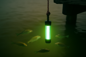
Executing code-compliant installation of a submersible dock fixture demands equipment engineered to withstand the environment — specifically, a unit where the seal separating the internal housing from electrical terminations remains absolutely impermeable. The Tendelux model addresses the portion of this problem that wiring methodology cannot: engineering designed explicitly to exclude moisture from energized components.
What works
- Hardened epoxy construction establishes a barrier preventing aqueous penetration into the fixture’s internal cavity, providing redundancy against installation errors
- Integral cable entry port removes the requirement for post-purchase drilling and custom sealing — one reduced source of potential water ingress
- Light output delivers adequate dock illumination without requiring excessive electrical demand, maintaining manageable amperage and limiting thermal generation within the fixture
What doesn’t
- Correct wiring execution remains your obligation — the fixture cannot compensate for deficiencies in conduit installation or missing grounding conductors
- The spectrum leans toward warm amber tones (fish-attracting characteristics, not a deficiency but significant if your goal is neutral white dock ambience)
I’ll admit, the first time I opened one up to inspect the internal seal before recommending it, I was half-skeptical—but seeing that epoxy barrier and the way the cable passes through a solid grommet changed my mind fast. If you’re serious about doing this right, grab the Tendelux Underwater Fishing Light.
Frequently Asked Questions
Can I use standard household Romex cable for dock lighting?
No. Never use standard interior NM-B Romex for any part of a submersible light assembly. The outer sheath fails under combined UV and moisture stress in roughly two years, exposing interior conductors to damp. Use 12/2 or 12/3 UF-B cable instead, engineered specifically for permanent water exposure.
What size GFCI breaker do I need for dock lights?
Install a 20-amp GFCI breaker within your main service panel, or position a certified 20-amp GFCI outlet rated for outdoor conditions at the principal receptacle on the dock. Both ABYC E-11 and NEC 553.10 specifications mandate GFCI protection for all 15- and 20-amp circuits around dock areas.
How often should I secure dock light cable to structural members?
Affix your UF-B cable at regular intervals spaced no more than 24 inches, using stainless fasteners instead of galvanized alternatives, which corrode within a handful of seasons in saline water. Cable segments in sun exposure or high-traffic areas should be enclosed in liquid-tight protective conduit.
How do I make watertight connections on submersible dock lights?
Deploy marine-rated adhesive-backed heat-shrink butt splices at every termination point. After crimping and shrinking, encircle each connector with self-fusing silicone wrap followed by marine-rated electrical adhesive tape. Standard connector hardware will deteriorate in a single season of saltwater exposure.
Sources and further reading
About This Article

Written by Trent Hollis. Waterfront homeowner turned DIY obsessive. After two decades tinkering with my own dock, seawall, and boat lift on the Gulf Coast, I share everything I've learned about waterfront construction, boat lift maintenance, and coastal living projects. More about this site.
Scope and limits. Trent is a waterfront homeowner, not a licensed marine contractor. Structural, electrical, and lift work should go to a licensed marine contractor, and most in-water work needs a permit before you start.
Verify this against a primary source
Specifics change, and your situation may differ from the one described here. These are the authorities worth checking directly:
- ABYC — marine electrical and construction standards
- U.S. Army Corps of Engineers — permitting for work in navigable waters
- NOAA Tides & Currents — tidal range and water level data for your site